Chalkaat

Augmented reality laser-cutting

Sharma A., Liu L., Maes P. — Published at ACM UIST 2015
Sharma A., Madhvanath S., Billinghurst M. — Published at ACM ICMI
Chalkaat augmented reality laser cutter
Annotated schematic of the Chalkaat system architecture, illustrating the spatial arrangement of three principal components: (a) an overhead RGB camera and DLP projector for optical tracking, (b) a 2 W laser mounted on an XY gantry for material actuation, and (c) color-coded fiducial markers placed on the workbed for command differentiation.

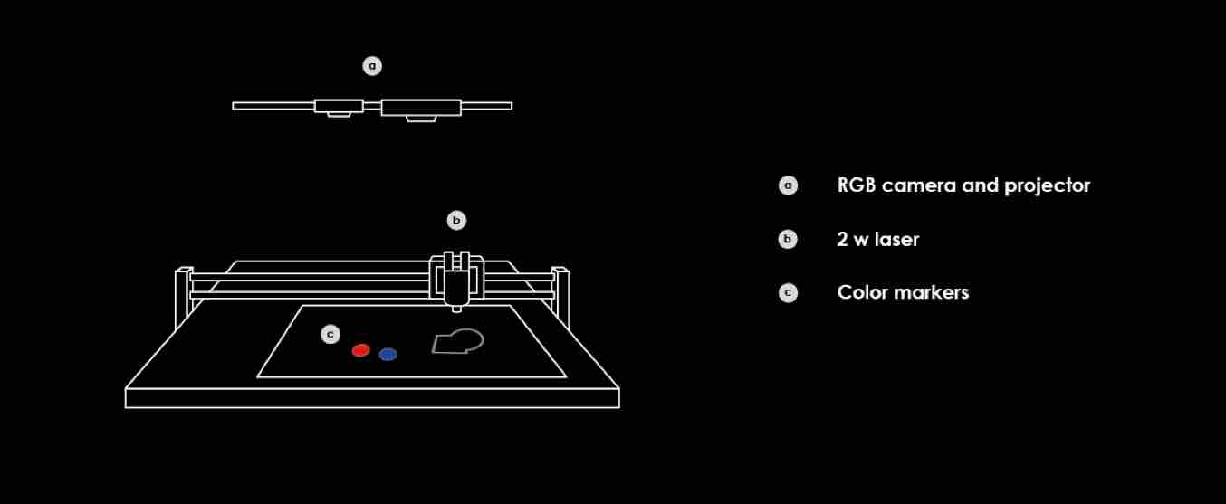
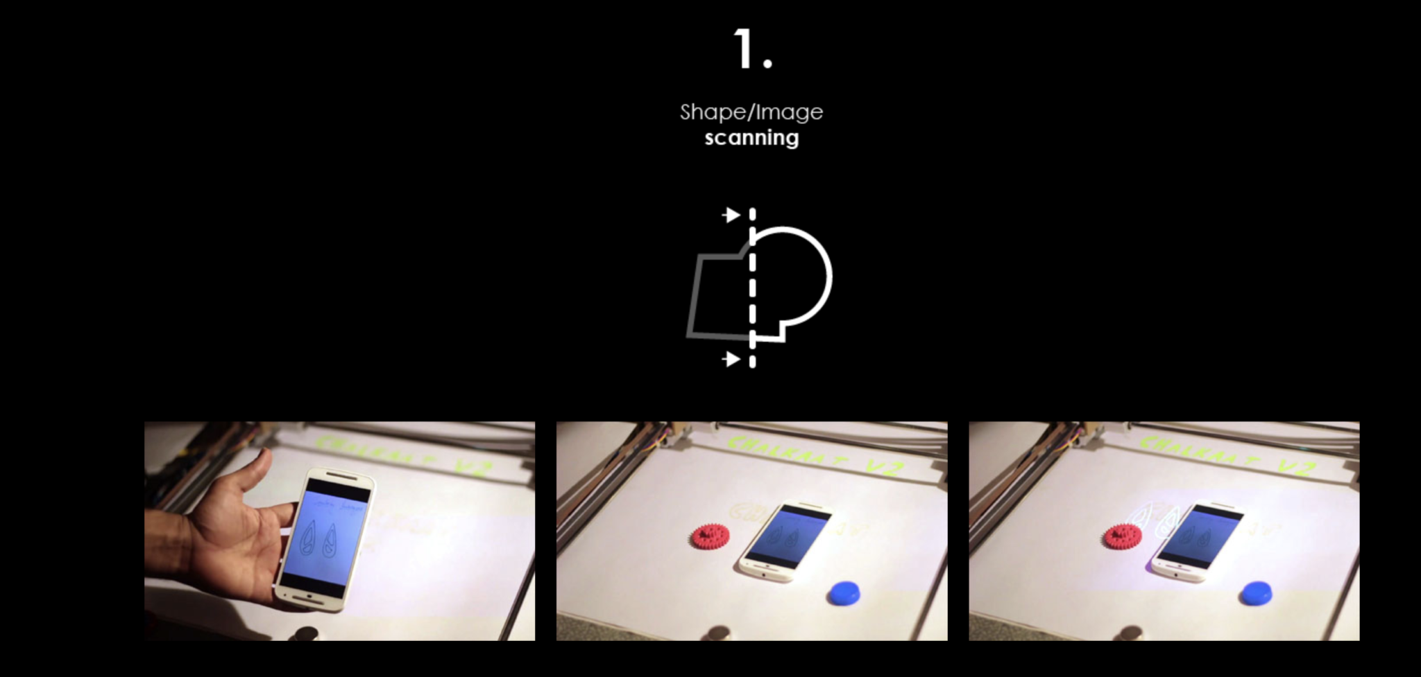
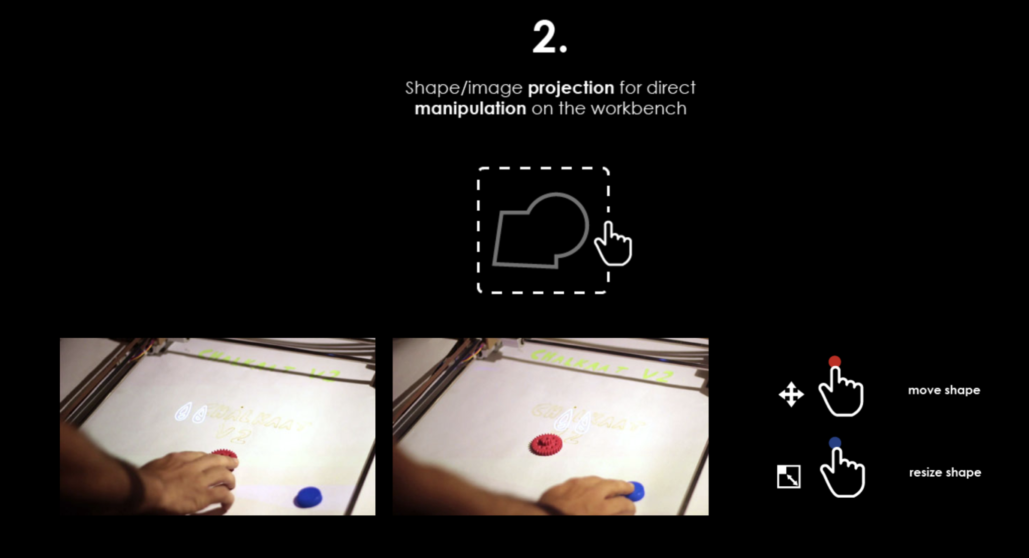
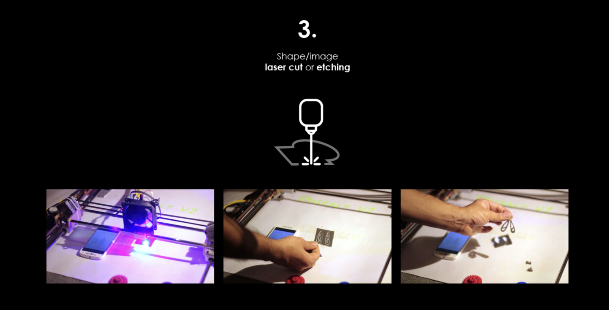
The system consists of a semi-transparent display and optical tracking interfaced with the laser cutter so that users can draw virtual graphics on top of their workpiece. The system also helps users to make virtual copies of physical artifacts, which can later be cut.

‘Computer-less’ UI for interacting with laser cutters, where the users can express themselves more directly by working directly ‘on the workpiece’. The camera on top tracks the strokes. Different colored markers allow different commands to be executed.

Chalkaat user interface
Perspective sketch of the Chalkaat user-interface configuration. An overhead projector and IR camera illuminate a semi-transparent projection screen above the laser-cutter bed, while an infrared laser with a 120-degree spread enables touch-free depth sensing of user gestures at the workstation.

The evolving field of personal fabrication holds much potential for the coming decade and laser-cutters allow fast and high quality cutting and engraving of a wide range of materials. Our system allows for direct manipulation with laser cutters.

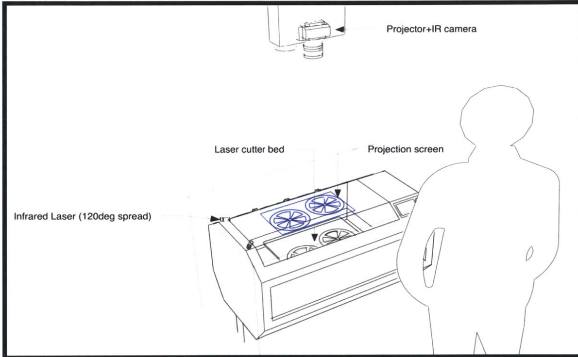
We prototyped the interface by building a laser cutter from the ground up, with DLP projection, computer vision and object recognition, stroke tracking.

In team with: Nitesh Kadyan, Meghana Bhat, Fabio Besti
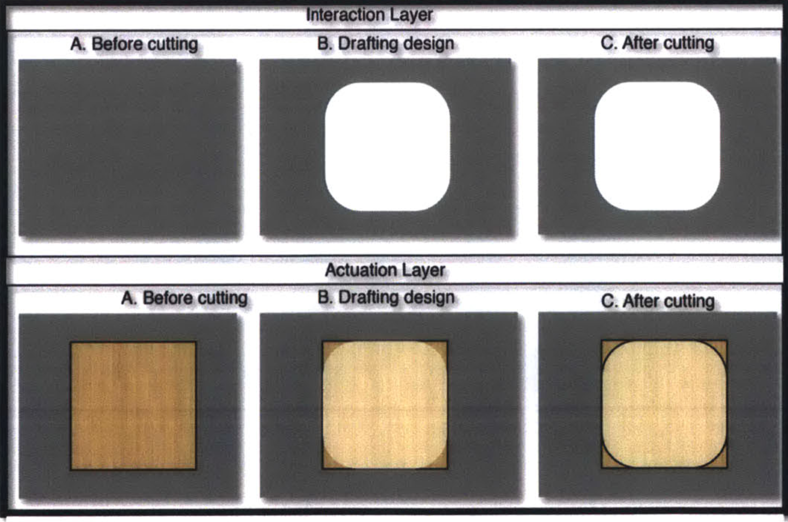
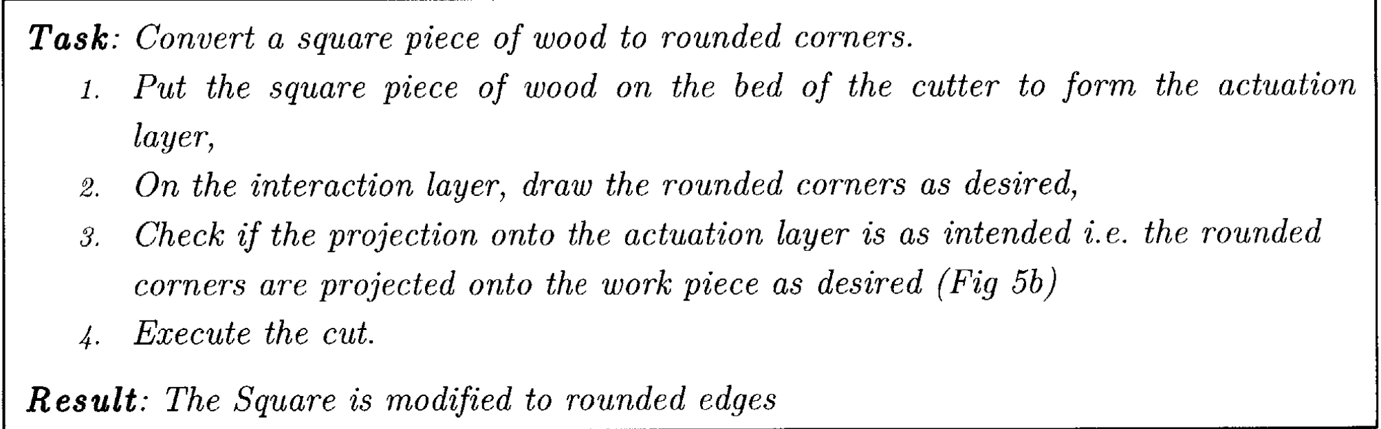
Chalkaat system layers
Comparative visualization of the dual-layer interaction model. The Interaction Layer (top) shows the virtual design progression on the semi-transparent display, while the Actuation Layer (bottom) shows the corresponding physical workpiece — a square wooden substrate whose corners are progressively rounded from initial state (A), through drafted cut-path overlay (B), to final laser-cut result (C).
Chalkaat augmented reality projection
Procedural task description for a representative use case: converting a square workpiece to rounded corners. The four-step protocol — placement, freehand drawing on the interaction layer, projection verification on the actuation layer, and cut execution — demonstrates the direct-manipulation workflow enabled by the system.
Chalkaat augmented reality laser cutter by Fabio Besti, Anirudh Sharma, Nitesh Kadyan
System assembly diagram attributed to the Chalkaat team (Fabio Besti, Anirudh Sharma, Nitesh Kadyan), showing the labeled hardware stack: overhead RGB camera and projector module (a), XY-gantry-mounted 2 W diode laser (b), and color-coded physical markers (c) used as tangible input tokens on the cutting bed.
Step 1: Shape and image scanning via smartphone placed on the laser-cutter workbench
Step 1 — Shape and image acquisition. A smartphone displaying the target geometry is placed on the workbed; the overhead camera captures and registers the design.
Step 2: Shape and image projection for direct manipulation on the workbench surface
Step 2 — Projected shape manipulation. The scanned geometry is projected onto the semi-transparent display; the user repositions using color-coded tangible markers.
Step 3: Shape and image laser cut or etching on material
Step 3 — Laser actuation. The 2 W diode laser traverses the programmed cut-path, producing the finished laser-cut and etched components.